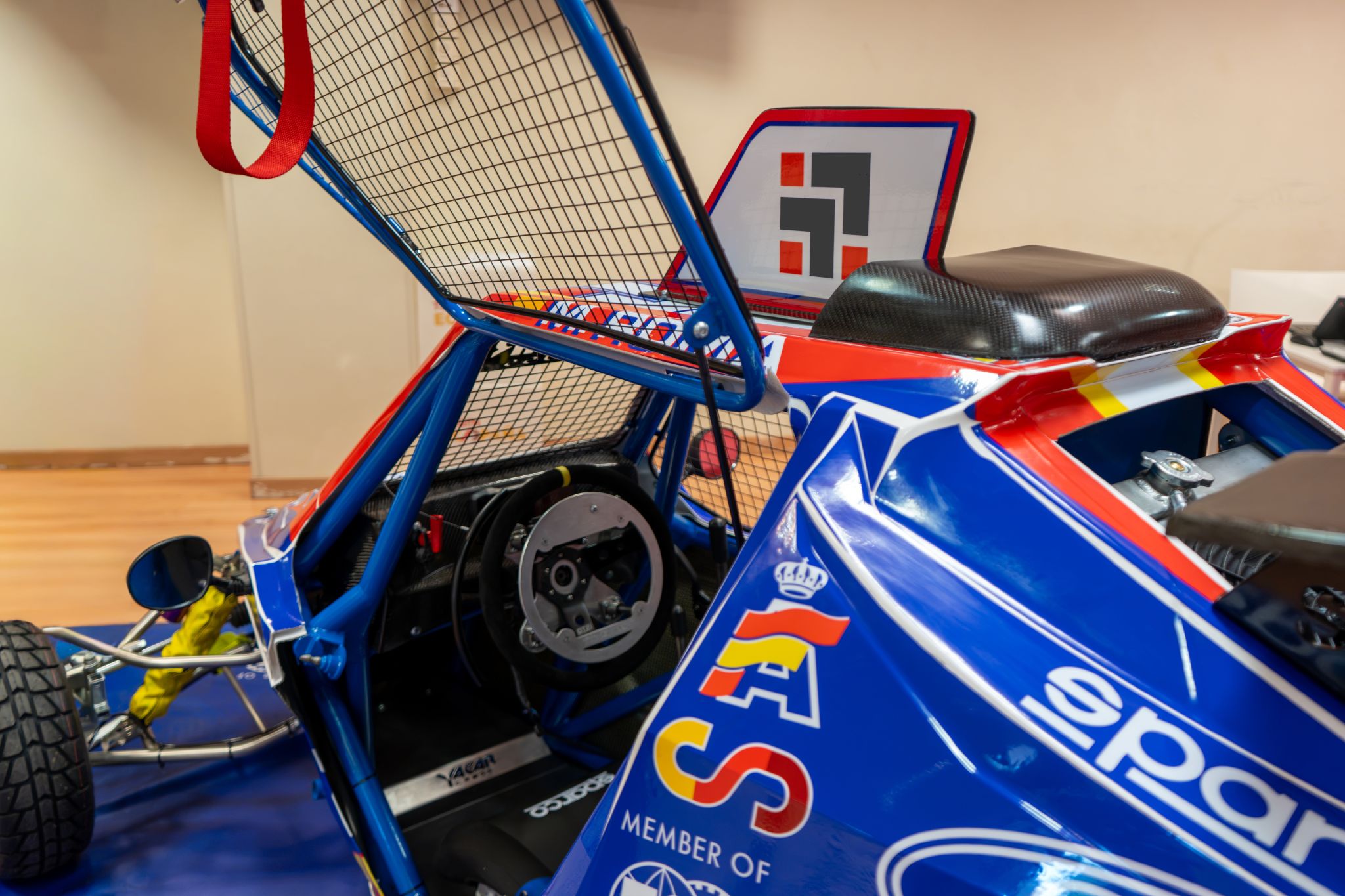

Can a motorsport vehicle be adapted for drivers with reduced mobility without compromising safety?
The first FIA-endorsed adapted Cross Car, unveiled by the Real Federación Española de Automovilismo (RFEDA) in 2026, set out to prove it could. Managing Composites evaluated the structural performance of both the original and adapted chassis using Finite Element Analysis (FEA) and FIA-approved load cases, assessing whether accessibility could be achieved without compromising safety.
Engineering the First FIA-Endorsed Adapted Cross Car
On the 29th of July 2026, the Real Federación Española de Automovilismo (RFEDA) unveiled a very special and unique vehicle: the first ever Cross Car approved by the Fédération Internationale de l’Automobile (FIA) adapted for drivers with reduced mobility. They can get in, get out and, of course, race. As part of the initiative, Managing Composites were responsible for the structural assessment behind it through Finite Element Analysis (FEA), alongside Yacarcross, who manufactured the first two units, Guidosimplex, who developed and integrated the adapted driving controls, and PCR Sport, who handled technical integration and set-up.
The objective was never a protected class or a compensated ruleset. It was to open up a competition chassis without relaxing the safety standards required of any competition chassis. In a Cross Car that is a structural problem, not an ergonomic one, which is how Managing Composites, one of the very few companies in Spain that is certified by FIA to assess the structural performance of safety cages for motorsport applications, came to run explicit simulations on a steel tubular frame.
Why the cage is the critical part
Cross Car, also known as car cross , is one of the best entry points international motorsport has: a lightweight tubular frame, rear-wheel drive, a high-revving motorcycle engine, and a power-to-weight ratio close to 0.5 hp/kg. It sits within the FIA European Autocross and Cross Car Championship and it is one of the fastest-growing routes into international competition, largely because it is affordable. A discipline that is cheap to enter is a sensible place to work on who can enter it.
However, it is also hard to modify. In most race cars you can draw a line between the chassis and the roll cage. In a Cross Car you cannot:
- The chassis is the multi-tubular spaceframe that consists of the safety cage, its compulsory reinforcement tubes, and the tubular structure welded to them.
- The cage is required to be an integral part of that chassis.
- There is no subframe to re-bracket and no floorpan to drill; there is no structure that is not also the survival cell.
So to let a driver with reduced mobility enter and exit, the tubular structure needs to be modified around the cockpit, and that structure is what protects the occupant in a rollover or a side impact. Adapting the car and validating the cage are the same job.
The brief: five load cases, two frames, identical conditions
The design modifications, loading scenarios and boundary conditions were proposed by the RFEDA and approved by FIA. In particular, load cases were based on the FIA 2025 Homologation Regulations for Safety Cages. Following the methodology that led Managing Composites to be included in FIA Technical List 35, two numerical models were developed: the original frame and the adapted one. Both models were run through the same set of tests in order to compare their performance.
Five stamp positions were studied on each frame:
- Load Case 1 — vertical load on the main roll hoop.
- Load Case2 — inclined load on the front roll hoop.
- Load Case3 — side load at the most forward point of the horizontal lateral member.
- Load Case4 — side load at the middle point of the horizontal lateral member.
- Load Case 5 — side load at the most rearward point of the horizontal lateral member.
In every case the frame was constrained at the longitudinal members 100 mm ahead of the front roll hoop and behind the main roll hoop, and loaded through a rigid stamp to fracture rather than to first yield.
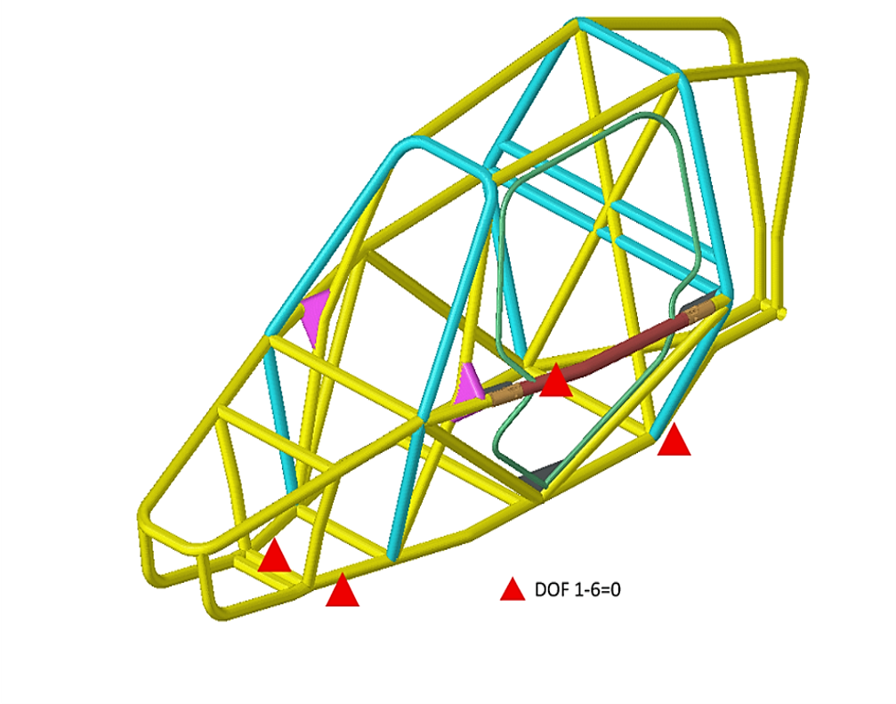
Load case definition: vertical load on the main roll hoop, inclined load on the front roll hoop, and side load at three positions along the lateral member.
Inside the model
All parts were modelled as surfaces and meshed with 2D shell elements carrying the tube thicknesses from the received CAD. Element size was selected based on a sensitivity study. A general contact algorithm handled the interaction between stamp and structure, and self-contact was added on the adapted model so the simulation could capture how the modified door structure interacts with the main frame under load. The analyses were run in explicit solver Siemens (formerly Altair) Radioss 2025.
The frame material was structural steel S355J2, defiined with a full elastic-plastic curve so the models could be pushed to fracture: 210 GPa Young’s modulus, 355 MPa yield, 800 MPa ultimate, 22% strain at break.
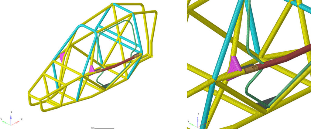
Modelling detail. Shell mesh at 5 mm, with self-contact on the adapted model to capture the door-to-frame interaction.
What the simulations showed
Under the vertical load on the main roll hoop, the case that represents a rollover, the adapted frame reached a 21% higher failure load and absorbed 63% more energy. Under the rearward side load it was also stronger, by 23% on failure load and 11% on absorbed energy. Under the inclined front roll hoop load the two frames were effectively identical, within 2%.
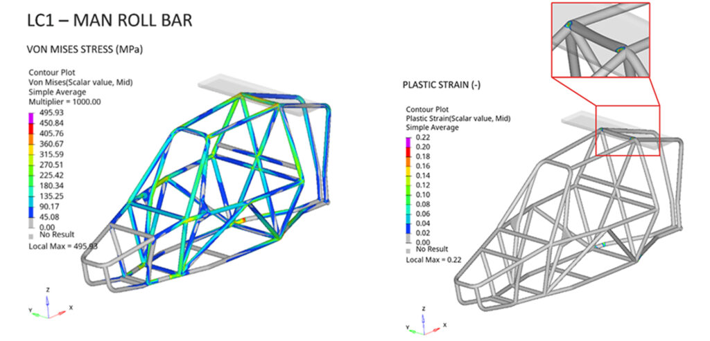
Von Mises stress and plastic strain in the adapted frame under Load Case 1.
Similarly, the forward and mid side-load cases went the same way. Under the forward side load the adapted frame failed at 36% higher load, and under the mid side load at 6% higher load, absorbing more than twice the energy in the mid side case.
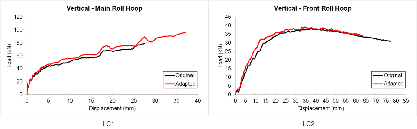
Load-displacement response of the original and adapted frames, Load Cases 1 and 2.
Load, displacement and intrusion
A comparison of percentage differences is not, on its own, a verdict on occupant safety. For a survival cell the governing question is not which frame carries the higher load, but whether the maximum displacement stays within the maximum allowable intrusion that guarantees the occupant’s safety.
This works in both directions. A frame that reaches a lower peak load while deforming further can, depending on the case, subject the occupant to a lower deceleration. A higher failure load means little if the structure has already intruded into the space the driver occupies. Load and displacement have to be read together, against a defined intrusion target.
The final assessment therefore compares both frames at equal load, taking the lower of the two failure loads for each case as the baseline, which was the original frame’s every time. On that basis the adapted frame displaced less in all five load cases: 6% less under the vertical main roll hoop load, 13% less on the front roll hoop, 7% less at the mid side point, 65% less at the rear side point and 92% less at the forward side point. At any load the original structure can survive, the adapted one deforms into the cockpit less than the structure it replaces. A unified target for load and displacement, meaning an explicit maximum allowable intrusion, would let future adaptations be assessed against a fixed criterion and not only against the baseline they replace.
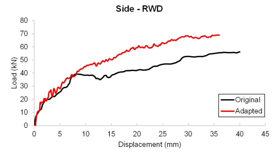
Load-displacement response of the original and adapted frames, Load Case 5.
Inclusion without a separate category
The FIA’s framework for adapted vehicles rests on three conditions: an adaptation must be safe, it must be based on the individual needs of the driver, and it must not confer a performance advantage. The third condition is what makes the first two worth having. Where a car is given an allowance, its results carry an asterisk. Where it carries no advantage, the timing screen means the same thing for every driver on the grid.
The regulatory work on this project was coordinated by the RFEDA Technical Department under its director Fernando Álvarez and homologation engineer Héctor Atienza. It was originated by Albert Llovera, driver and member of the FIA and RFEDA Inclusive Sport Commission, who defined what the car actually needed to do for the people who would drive it, and driven forward by Joan “Nani” Roma. During the unveiling, Nani’s son Marc demonstrated the access system, the adapted controls and the car itself at the presentation. At the moment two units exist, and more are expected.
MC perspective
At Managing Composites, we spend most of our time making structures lighter, stronger and more predictable. On this project the same tools contributed to something different: whether a driver with reduced mobility could actually get into the car and race any rival in the exact same category and with the same level of safety.
Simulation was worth doing here because the answer was not obvious. Cutting an opening into a welded spaceframe looks like it must weaken it, and the reasonable expectation was a trade: easier access in exchange for some structural margin. The calculations showed there was no trade to make, which is the kind of information that is only useful before anything is welded.
Cross Car matters beyond this one car because it is where drivers are found. If an entry-level FIA single-seater can be adapted without a category of its own, without a compensated ruleset and without a separate podium, the argument that inclusion requires segregation gets weaker at every level above it.
For organizations involved in motorsport safety assessment, projects like this also demonstrate the value of simulation-led validation in answering critical engineering questions before physical prototypes are built.
Managing Composites, an engineering consultancy included in FIA Technical List Nº35, carried out the structural assessment in collaboration with RFEDA and Yacarcross.